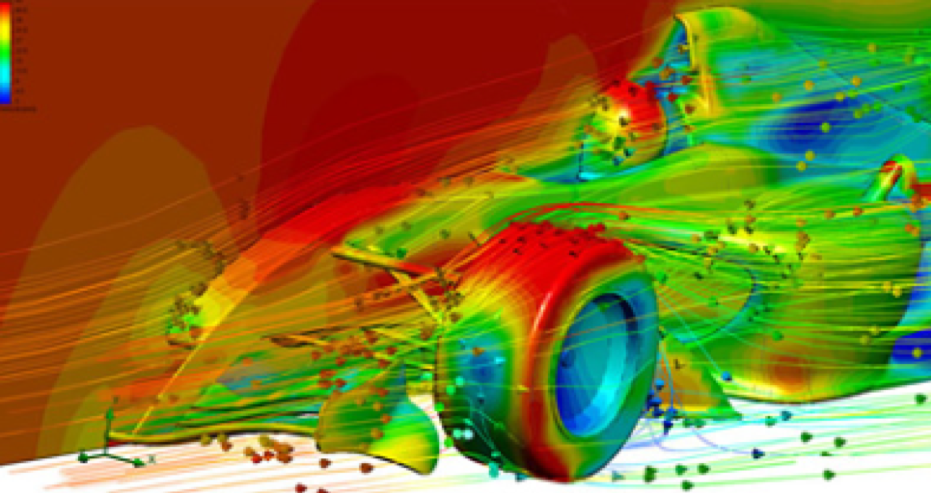
Computational Fluid Dynamics (CFD) has gained momentum since the late 20th century. Its strength as a high-fidelity predictive software combined with powerful graphics allow visualisation of multi-dimensional problems. The visualisations are often helpful in pin-pointing an issue relating to physical flow behaviour of fluid particles and their interactions with the surroundings. As such, many people are familiar with it as a tool for analysing air flow around race cars as shown in Figure 1.

Figure 1: Surface velocities on race car body showing flow trajectories (Source: Published by Mentor Graphics – courtesy of Voxdale)
In offshore engineering, CFD has found a niche area in offering both insights and foresights for complex problems. A few examples of the applicability of CFD, particularly within the Flow Assurance discipline are to examine:
- Maximum erosional velocity in pipelines (especially in small tubes and elbows when solids are present).
- Sand transportation phenomena.
- Cooling performance of subsea coolers.
- Minimum operating material temperature (e.g. during cold restarts).
- Effect of damaged insulation.
- Cooling rates in well tubing (due to complex thermal interactions with its environment).
- Subsea pipeline leakage dispersion modelling.
- Reduce sloshing in liquid separators on floating platforms.
However, due to the complexity of its internal mathematics, CFD simulations are processor-intensive, which leads to substantial computational time and modelling cost. Consequently, it takes careful consideration to determine when, where and how CFD should be employed.
Drivers for the use of CFD
To determine if the use of CFD is appropriate, one must first consider the drivers for the use of CFD. These drivers are not confined to strictly Flow Assurance concerns from a technical standpoint, but could also include drivers at a project level in terms of:
- Value gained through cost effectiveness.
- Value gained in improved risk management strategies.
Value in cost effectiveness could include CFD results enabling the design of smaller and lighter equipment, or enabling simpler and cheaper installations.
Value in risk management could include better definitions on the impacts of uncertainties, enabling the improvement of equipment performances, enabling an increased in operational flexibility or a better quantification of environmental risks so that appropriate measures could be taken.
In each case, the value could be estimated beforehand to justify the use of CFD simulations.
It is also of note that CFD tends to find little use in the space of Conceptual design in the Oil and Gas industries. Instead, its applications are more widely found during Detailed Design, where value improvement and risk reductions are key to success of the project or in trouble-shooting of installed plant.
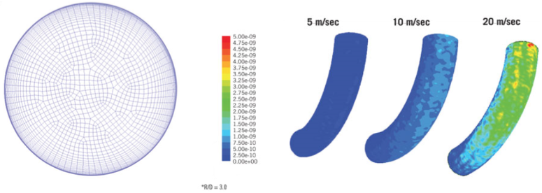
Figure 1 shows an extract of a published work (Oil and Gas Journal) typical of a Flow Assurance study performed to address operational concerns. The work predicts the erosion rates in pipe bends due to the presence of black powder in a sales gas pipeline. The black powder was found during gas sampling and displays hard and jagged i.e. erosive characteristics, suggesting the potential of erosion failures, particularly around pipe bends where particle impingement occurs. CFD was used to model the pipe bend and the effects of a range of variables were investigated, including pipe diameter, gas flow rate and pipe bend radius. The study was able to determine the velocity and concentrations profiles of black powder, as well as to conclude that the erosion rates caused by black powder are negligible and hence, not a concern. In this example, the use of CFD has added value in supporting decisions surrounding risk management of operating assets.
Figure 1: Erosion Rates on Pipe Bends

Left: Cross-section of the pipeline model showing the mesh setup for computation. Note the closeness of grids near the pipe wall, which is required to capture high-velocity gradients in that region. Right: Erosion rate (kg/m2-s) predicted in a pipe bend due to the presence of black powder in sales gas (particle sizes ranging from 2-20um). The erosion rates are clearly higher when the gas velocity is higher. Note that CFD also allows visualisation of where the impact zone is likely to be.
Source: Oil & Gas Journal, “Pipe diameter does not affect black powder distribution, erosion”, Ehab Elsaadawy and Abdelmounam Sherik (Saudi Aramco)
Limitations of CFD
As with any Flow Assurance simulation tool, one should be mindful of the limitations of CFD. In a generic workflow, the following components are expected:

Depiction of a Generic Simulation Workflow
Clarity should be sought in every aspect of the workflow to minimise the errors and uncertainties of the results obtained and to ensure that those results are produced on time. Those questions may include:
- What is the relevant experience of the analyst?
- What are the model boundaries?
- What are the input variables?
- What are the simplifications required (such as simplification by symmetry) in order to strike a balance between modelling time and accuracy of the information obtained?
- What could be done to reduce numerical errors with respect to the discretisation of space grids (meshing), time steps and iterations?
- Will there be a cumulative effect of errors by ignoring ‘negligible’ terms?
- Have the right algorithms been implemented correctly?
- Could computation time impact on project schedule?
- Is there a way to benchmark or verify the CFD results to help with interpretation?
- What is the range over which CFD results are applicable? Is this range wide enough to solve the problem at hand?
Even as the CFD industry continues to mature, it should be recognised that the results of a CFD simulation are never 100% reliable because:
- The input data may involve some form of guessing or imprecision.
- The mathematical model is not mechanistic enough to describe the problem.
- The accuracy of the results is limited by numerical errors which are inherent to digital computation.
Future of CFD in Oil and Gas Industries
The role of CFD pertaining to Flow Assurance in the Oil and Gas industries is expected to grow as the number of brownfield projects increases, requiring detailed studies for troubleshooting, debottlenecking and/ or optimisation.
CFD can also be expected to continue its contribution towards improving energy efficiencies of process equipment such as the gas turbine combustors and heat exchangers, to achieve lower emissions of pollutants such as NOx and greenhouse gases, as well as lowering operational costs.


