For many field developments and challenging export system projects, flow assurance is one of the first and most crucial activities to be undertaken. Peritus has in-depth knowledge and extensive experience in dealing with the most complex flow assurance problems.

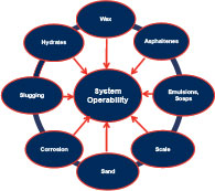
Typically, the flow assurance work was undertaken by Peritus during project design engineering phases broadly covers the following activities:

Flow assurance capabilities include:
- System design including networking and thermal-hydraulic simulation to assess layout credibility
- Thermal/hydraulic analysis of individual pipeline systems and networks, both steady state (PIPEFLO) and transient multiphase (OLGA)
- Product flow related issues such as slugging prediction, slug catcher sizing and slug catcher design
- System operability design including simulations for steady state flow, planned start-up/shut down, emergency shutdown and other unplanned scenarios, HIPPS studies
- Hydrate prediction, inhibition, and remediation
- Product chemistry related issues such as scaling, waxing and asphaltenes
- Solids deposition e.g. sand production
- Preparation of operating and maintenance manuals
Whenever possible, the emphasis is always placed in taking a systems engineering approach when organising the flow assurance work plan for example:
- Gather basic design information to define the modelling constraints for the system interfacing with Sub-surface, Completions and Host facilities process disciplines
- Steady state thermal-hydraulic flow modelling of multiphase pipeline and riser transport systems to select optimum pipeline sizes or to verify pipeline sizes, insulation requirements, flag potential flow assurance issues such as unacceptable slugging behaviour, excessive J-T cooling, hydrates/wax risk whilst interfacing regularly with both mechanical design and process disciplines
- Identify early to relevant disciplines possible areas to improve system flow performance e.g. wellbore gas lift optimisation, line size optimisation, drag reducers etc and also flag any operational constraints or bottlenecks to be resolved e.g. available FWHPs, arrival pressures and temperatures
- Dynamic simulation modelling studies to confirm slugging and hydrate/wax risks and system operability covering the full range of production operations, both steady state and transient scenarios
- Provide pressure /temperature/velocity profiles, slugging characteristics in terms of expected mean and maximum slug volumes and associated slug velocities to materials and mechanical design disciplines to assess erosion/corrosion, slug loads and forces on bends and piping supports, subsea pipeline and riser dynamics
- Provide production oil/water/gas outlet flowrates and velocity time histories to the Host Facility Process Design disciplines as input to topsides dynamic modelling activities to investigate system performance operability/stability and process control systems tuning
- Provide input to process disciplines on chemical injection rates and chemical storage volumes (e.g. hydrate and wax inhibitors), liquid surge volume handling requirements for slugcatcher or 1st stage separator and export pumping requirements and any liquid surge handling requirements at reception facilities
Thermal-Hydraulic Simulations
The depth of flow assurance analysis required depends on the engineering phase.
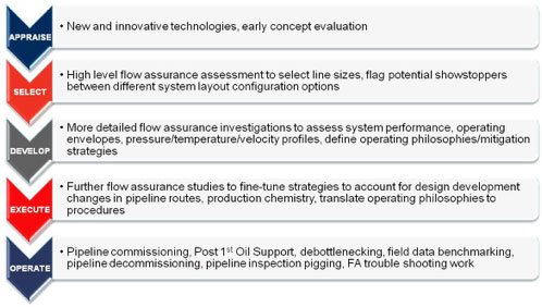
During the APPRAISE and SELECT phases, the thermal-hydraulic simulation scope of work undertaken by Peritus is designed to produce a high level assessment of the system performance as a basis to compare different concept options in terms of line sizes to meet thermal performance and deliverability requirements and system operability such as hydraulic stability, hydrates, wax and pigging as typically shown in Figure 2.1.
During the DEVELOP (including Front End Engineering Design) and EXECUTE (Detailed Design) phases, further flow assurance studies are undertaken to confirm the system performance for the selected concept. The thermal-hydraulic simulation scope of work is designed to establish the operating envelope for the system within boundary limits on available system pressure, erosion velocity, avoidance of wax deposition, avoidance of hydrate formation and avoidance of severe slugging during normal operation
Hydrate Prediction, Inhibition, and Remediation
The prediction of hydrate formation temperatures/pressures and the design of the overall system to prevent plug formation during system start-up, steady state operation, and shutdown (both controlled and uncontrolled) are fundamental to the design and operability of subsea production systems.
The selection of the optimum hydrate management strategy for the system usually involves a review of thermal and chemical management strategies. For gas dominated production systems, the strategy to prevent hydrate formation is typically using hydrate inhibitors on a continuous basis with a recovery unit. For oil dominated production systems, the typical strategy involves some combinationof keeping the fluid warm (insulation) during normal operation and either hydrate inhibition, electrical heating, depressurisation or fluid displacement strategies to handle extended shutdown and restart operations.
Further analyses are performed to determine the thermodynamic hydrate inhibitor (THI) dosage (using methanol or glycols) to avoid hydrate formation following an extended (unplanned) shutdown. The use of alternative ‘low dosage’ hydrate inhibitors (LDHI) such as kinetic hydrate inhibitor (KHI) and anti-agglomerate hydrate inhibitor (AA) are also considered. At Peritus, the current state-of-the-art in LDHI performance is regularly tracked.
Production Chemistry Issues Such as Wax and as Asphaltene Deposition
Chemical inhibition issues strongly influence flow system design, chemical inhibition design, and system operating philosophies/strategies and procedures.
Peritus has the expertise to determine the most reliable design/operating technique to manage these solid deposition issue including using system insulation (to retain heat, reduce the radial temperature gradient, reduce the temperature difference between fluid and pipe wall) and regular pigging to limit the amount of wax that does accumulate. This is especially true if insulation is needed for other reasons (including hydrate control). It is often prudent to include injection capability in the system design so that chemicals can be injected if found to be necessary.
Slug Prediction and Slug Catcher Sizing
Liquids management of onshore and offshore production systems often require provision of a slug catcher in order to provide system flexibility to manage normal operational (regular or severe) slugging, rate change/start-up slugs as well as large liquid slugs removed as a consequence of a pipeline pigging operation if deemed to be a requirement.
For offshore floating and/or platform-based systems in particular, slug catchers may not be desirable due to weight and space constraints. Where possible, and particularly for oil/gas systems, it may be preferable to use separator inlet chokes (possibly brought into play by the level control circuitry) to control separator liquid inflow, oil/water drainage rates to be within the surge volume handling capacity.
During the conceptual design phase, an initial assessment of the slug catcher surge volume handling requirement for rate change operations can be quickly performed by Peritus using the Cunliffe method (as this method only requires output data of the steady state liquid content in the system). For SELECT and EXECUTE phases, more detailed analysis is performed by Peritus to verify the slug catcher size using transient simulation to confirm the maximum surge volume generated from rate change operations (and from hydrodynamic slugging during normal production
An initial assessment of pigging requirements is carried out using to obtain predicted liquid volumes resulting from pigging or ‘sphering’ operations.
Production/Flow System Operability
The Peritus flow assurance team have considerable expertise in the assessment of system operability issues where the primary objective is to develop operating philosophies, strategies and procedures to avoid hydrate or wax formation at any time during system operation. “Operability” means ensuring that design provisions and operating strategies are in place so that the production system can be started, operated, and shut down under all conditions (planned and unplanned) throughout the operating life of the total system and is central to the overall Flow Assurance/System Design Process.
A major effort early in the design process will be to establish the design basis. All aspects of the system, such as fluid characteristics, reservoir behaviour, site characteristics, and host facilities will be reflected in the design basis. The design basis should include sufficient conservatism to offset poor or missing data. The Peritus team has the experience to help avoid unnecessary conservatism.
During the early stages of engineering design, where a considerable percentage of the system input data has been either taken from similar project analogues, the results and conclusions drawn from the simulation results will be relatively cursory. As the system design moves into SELECT and EXECUTE phases, the flow assurance effort will shift towards more detailed analyses to support operating procedure development and hardware and facilities designs and evaluations.
Carbon Capture and Storage (CCS)
With the world’s current dependence on fossil fuels and ever increasing energy demands in emerging economies, the control of carbon dioxide emissions into the environment has become an important focus area for all countries in response to the global movement to address climate change. Carbon Capture and Storage (CCS) is the commonly used term to describe the process for capturing carbon dioxide (CO2) from large industrial sources such as coal-fired power stations and oil & gas refineries before it is released to the atmosphere, and to safely transport the CO2 either for storage in mature oil and gas reservoirs, deep geological formations such as aquifers or for enhanced oil recovery (EOR) operations in existing fields.
Peritus has been involved in several CCS projects to assess flow assurance issues in CO2 pipeline transport systems. For single component fluid systems where there is no phase envelope or, even if minor impurities (< 2%) are present, the phase envelope is very narrow and hence phase changes will be abrupt and result in very sudden change (or non-linearity) in fluid properties at pressure/temperature conditions straddling its saturation line or phase boundary. Such abrupt changes cause numeric instabilities using the basic OLGA® solver whilst with the single component solver, advanced numerical smoothing algorithms have been developed to cope with the non-linear changes in fluid properties around these regions.
Methane Hydrates Production
Methane hydrate deposits found in deep oceanic regions and under the Arctic permafrost are regarded as the gas resource for the future. These deposits are typically several hundred meters thick, formed as a result of either biological activity in sediments or geological processes deeper within the earth. Hydrates can be dissociated by either lowering the pressure (the ‘depressurisation’ method) or increasing the temperature (the ‘heating’ method).
Presently gas hydrate R & D programs are being conducted by US, India, Korea and Japan to determine the most efficient production method for recovering methane gas. To-date, small scale production tests have been successfully carried out in the U.S. and Canadian Arctic with large-scale production tests currently being planned in the U.S. Arctic and in offshore Japan.
Peritus has experience in providing engineering design support in this R & D area in offshore Japan where methane hydrates deposits are present in ca. 100m to 300m below seabed in water depths ranging from 700m to 1000m.
Peritus has been involved in the conceptual design of a production test facility to produce dissociated methane gas and water from production test wells to a vessel via an infield subsea production system. Hydrates are dissociated using the ‘depressurisation method’.
The flow assurance issues associated with this production scheme are:
- Risk of hydrates reforming in the production well, gas and water lines during normal production
- Risk of two-phase flow and slugging in the separated water lines
- Risk of water condensing out in the gas production lines and generating potential slugging over the range of flowrates and
- Risk of hydrates reforming during initial start-up, shutdown, and restart operations.
The primary Flow Assurance and analysis tools used by Peritus are:
- PIPEFLO® and WELLFLO® (with ATI® or VMG® PVT) – SPT Group
- OLGA® (with PVTSIM®) – SPT Group
- FLOWMASTER®
- The above software tools are used for detailed flow and heat transfer modelling and analysis of insulated systems. Other specialised modules in OLGA® (such as Wax, Compositional Tracking) are used where/when needed. Peritus personnel have experience with other analysis tools including NATASHA®, PIPENET®, SPS®, PIPESYS®, HYSYS®, PRO II®, FLARENET®.
- Where required, the following alternative steady state multiphase flow software tools are also used
- PIPESIM® and PIPESIM-NET® (with MULTIFLASH® PVT)
In addition to discipline engineering roles, Peritus can and has provided Project Management Services in the form of provision of owners engineering teams, supervising the EPCIC contractors during Develop and Execute. Peritus are able to use their own management and project support systems if required. Peritus’ Management Systems are certified to ISO 9001.


