Offshore pipeline installation is costly wherever it is performed but especially so in regions with high labour costs and/or distant from the major offshore working hubs. Conventional installation methods (S Lay) typically require crew sizes of 250-350 personnel offshore for extended periods of time plus considerable support . This article explores alternative installation methods some under development and some admittedly would be considered ‘fanciful’ but nevertheless will hopefully spark some innovative thought.
The focus is on identifying methods that allow labour intensive activities to be undertaken in low cost centres and for installation methods that are less reliant on highly specialised equipment.
The current S Lay and J Lay installation market has seen a significant amount of new investment over the last 5 years with many new vessels entering or about to enter the market. A selection of these is presented in Table 1.0. The table is limited to vessels with higher tension capacities. While there are many vessels, most are based in Europe with many owned by 2 contractors.
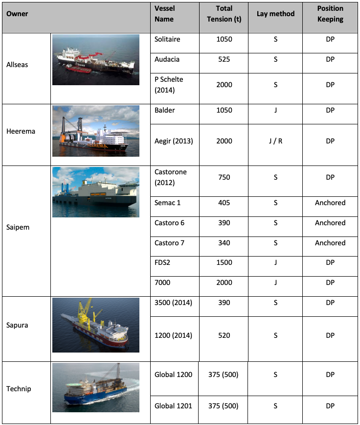
Table 1.0 – Typical 3rd / 4th Generation Laybarges
Conventional S lay and J Lay offers a proven and reliable method to lay pipelines but at significant cost. Adoption of this installation philosophy provides a predictable outcome and in terms of minimising risk to a project would be an attractive solution for most projects. In some regions there is a possibility that these elevated costs might render some projects uneconomic. It is therefore worthwhile considering what alternatives might exist. This article examines 4 alternatives and identifies their merits and shortfalls. The options include:
- Mega Reel Lay
- Floating Coil
- Floating Reel
- Towed Raft
Mega Reel (Carousel) Lay
Current reel lay technology is generally limited to 16-18 inch diameter pipelines and 3,000 tonne capacity reels. This typically limits pipeline lengths to a few kilometres after which the vessel needs to return to the spooling site to reload. The objective of the ‘Mega Reel’ is to develop a system that can extend the pipe diameter beyond 18 inch and to increase reel/carousel capacities to 15,000 tonnes or more to accommodate pipelines to 50km to 100km in length. Due to the size it is more probable that this concept would be based around a carousel than a reel.
The concept is to manufacture complete lengths of pipeline at one of the existing deck fabrication yards (low cost location site) and spool the pipe onto a mobile carousel for subsequent load out and transport to the installation site. Deck fabrication sites typically have the capacity to fabricate and load out structures in the range of 15,000 to 25,000 tonnes in weight hence a loaded carousel of 15,000 tonnes is considered feasible. Carousels already exist with 9,000 tonne capacity for cable lay so an increase to 15,000 tonnes is not inconceivable. The loaded carousel could be transported to the installation site using one of the heavy lift semi submersible transport vessels typically used for transporting large production decks, hulls and rigs (Figure 1).
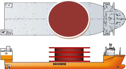
Figure 1 – Heavy Lift Semi Submersible Transport Vessel
There is an expanding market in these vessels with ever increasing capacity. There are many vessels in the range 20,000 to 50,000 tonne capacity and new vessels exceeding 100,000 tonnes capacity.
Once in the field, the transport vessel would need to transfer the pipe or complete carousel onto a specialist vessel with required positioning, straightener, tensioner and stinger facilities. The entire carousel could be transferred to the installation vessel by the ‘Float over’ method or if made buoyant then the carousel could be transferred in the water using tugs and pull in systems. Subject to weather conditions, the carousel could remain on the transport vessel and ‘raft up’ with a host vessel with suitable facilities to lay the pipeline.
Mega Reel lay could be supported by specialist semi submersible or catamaran vessels or utilisation of the emerging market in platform abandonment vessels. The Allseas ‘Pieter Schelte’ (Figure 2) due for completion in 2014 will have the capacity to support a payload of 25,000 tonnes on the stern and 45,000 tonnes on the bow. Such a vessel could conceivably be used to carry a large carousel and lay pipe using its existing systems. While still dependent on a specialist vessel the crew size and vessel time would be significantly reduced. Other vessels targeting the platform decommissioning market might also offer similar capability.
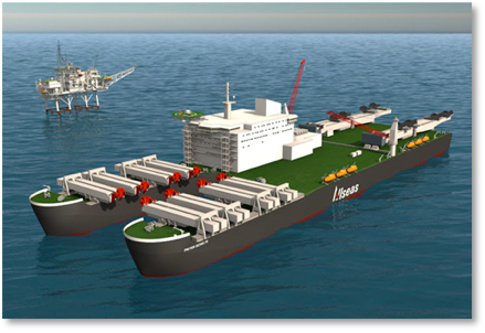
Figure 2 – Allseas Pieter Schelte
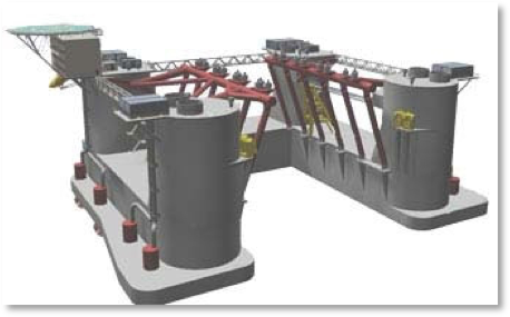
Figure 3 – MPU Enterprise – HL Semi (scrapped)
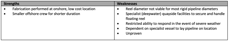
The strengths and weaknesses of the ‘Mega Reel Lay’ concept are presented in Table 3.0.
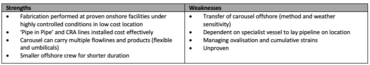
Table 3.0 – Mega Reel Lay Strengths and Weaknesses
Floating Coil
The floating coil concept has been under development for a number of years and is marketed by EuroSpiraal and ‘O’Lay. The concept is based on spooling pipe onshore and then pushing it offshore where it is buoyed and coiled on the sea surface for towing to the installation at site. The coil diameter is approximately 500 times the diameter of the pipe. Once at the offshore location the coil is unspooled, buoyancy removed and the pipe layed on the seabed. This is achieved using a barge with positioning, tensioner and stinger system.
Eurospiraal and Marin undertook a trial on behalf of Wintershall in Norway in 2008 whereby 1 km of pipe was spooled, coiled on the sea surface (100m diameter coil) and towed in order to measure the strains and associated fatigue imposed by a surface tow.
It is not clear what the status of this technology is at this stage. Peritus is not aware of any projects that have adopted this technique and it is understood that the companies are seeking further funding to develop the technology.
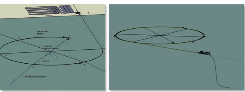
Figure 4 – Eurospiraal system
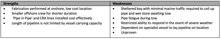
The strengths and weaknesses of this technology are presented below.
Floating Reel
This concept is conceived from the famous WW2 ‘Pluto’ project whereby flexible fuel lines were secretly fabricated onshore and spooled up onto large floating reels (Conun – drums). The fuel lines were laid between England and France by towing the reels across the channel while un-spooling the fuel lines onto the seabed.
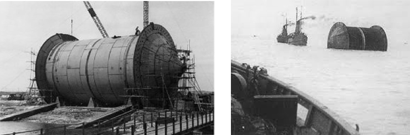
Figure 5 – WWII Pluto Project ‘Conun – Drums’
Adopting a similar approach for a 20 inch diameter pipeline would require a drum diameter of over 100m in order to maintain the pipe in an elastic condition. To put this into perspective a typical ‘Spar’ hull is of the order of 30-40m diameter. Although an intriguing concept it is unlikely this would be a viable means for laying medium to large diameter rigid pipelines. This could possibly be used for laying small diameter rigid lines or flexible lines. At the risk of taking this concept from the ‘fanciful’ to the ‘extreme’, consideration could be given to sinking the reel to the seabed to unspool the pipe and therefore avoid the need for a stinger and tensioner’s – subject of course to there being no environmentally sensitive areas along the route.
The strengths and weakness of the floating reel concept are presented below.
Pipeline Raft
The pipeline raft is essentially a variation of the towed pipeline technique which has been used to successfully install pipelines around the world for decades. Whereas several smaller diameter pipelines can be contained within a ‘bundle’ the raft concept is conceived for multiple larger diameter pipelines. Rather than installing pipelines individually the proposed concept is to install multiple pipelines over longer lengths (10 – 15km) by using the structural integrity of the pipelines and permanent buoyancy tubes in a ‘flat pack’ arrangement to make the longer systems viable. The pipelines and buoyancy tubes are held together by means of bulk heads at intervals along the raft. The intent is that the raft be installed via the off bottom /controlled depth tow technique, hence the positive raft buoyancy would be offset by drag chains.
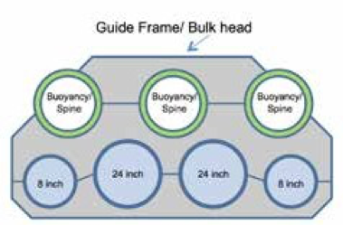
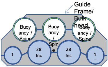
Figure 6 – Raft Cross Section (drag chains omitted)
The biggest advantage towed pipelines have over conventional pipelay, and the methods described above, is that it would not require specialised marine equipment to install. A typical towed pipeline marine spread would consist of 2-3 high powered tugs together with an MSV to support tie-ins and pre-commissioning. While the raft concept would clearly require multiple tow vessels of high capacity these are relatively non specialist vessels and can be quickly mobilised with small crews.
The raft also offers the ability to integrate risers, structures, monitoring and control systems, heating systems thereby minimising the need for offshore intervention.
An example of some of the benchmark towed pipeline systems, including a raft system, installed to date is presented in Table 4.0.
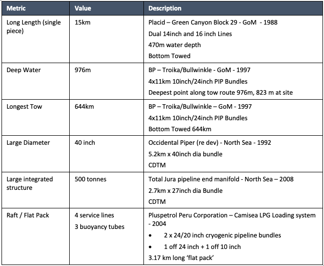
Table 4.0 – Example towed pipeline systems.
The majority of the long and deepwater tows were bottom towed pipelines, performed in GoM and fabricated on Matagorda Island (Figure 7). This location provided a somewhat unique opportunity to fabricate along the beach rather than the more common approach of perpendicular to the beach.

Figure 7 – Pipe Stringing on Matagorda Island, Texas USA
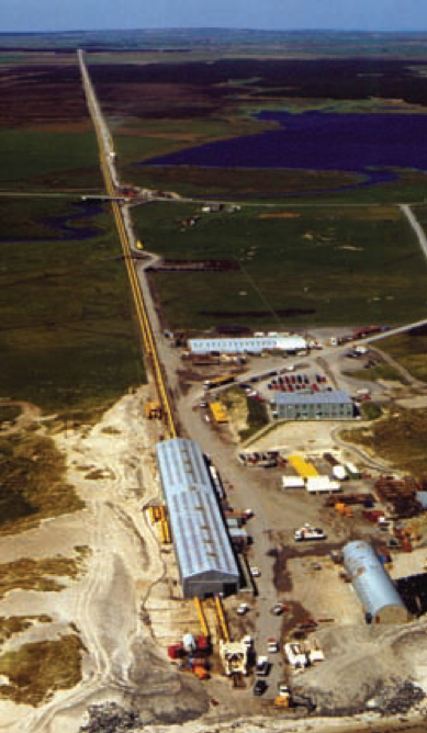
Figure 8 – Subsea 7 Wick Fabrication Site UK
A challenge with towed systems is to create a coastal fabrication site of sufficient length and with access to required infrastructure to receive, transport and store large quantities of materials. Towed pipeline systems ideally require a permanent stringing site (such as the 7.7km Subsea Wick site in the UK – Figure 8) although many projects have been undertaken using temporary project sites.
Once the raft is ‘flying’ then the system is capable of transiting long distances and deep waters. While it is envisaged that the pipeline would be towed at shallow depths there will always be a need to ‘park’ the raft on the seabed at any point along the tow in event of bad weather or similar contingency event. The wall thickness of buoyancy tanks to resist collapse in very deep waters (1000m) can be minimised by pressuring the tanks with inert gas.
Once on location the raft would revert to ‘off bottom tow’ for final positioning and the tanks flooded to provide the necessary stability. The tanks could be configured to allow future evacuation of the water to allow refloating of the raft and potential for re-use or salvage.
Tow distances of 1000km or more are not seen as unsurmountable and would enable considerable flexibility with stringing site location.
The relative strengths and weaknesses of the pipeline raft concept are presented below.
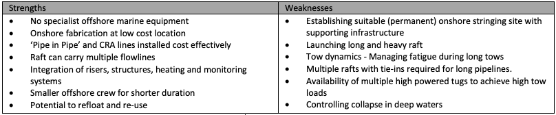
Table 7.0 – Towed Raft Strengths and Weaknesses
Conclusion
With few exceptions the industry is doing little to encourage development of alternate pipeline installation techniques. Significant money is being invested by the major contractors into refining the existing technologies but little is being done to explore alternate methods that may offer significant cost benefits. Rationalisation of the pipelay contractor market reduces the choices available. Promoting new installation methods would allow non traditional pipelay contractors to enter the market thus providing a greater level of choice and competition. Given the need to extract reserves from deeper water and more distant locations the need for cost effective pipeline installation is a necessity to ensure installation costs do not render projects uneconomic.
New techniques will require time and investment to validate and mature into a viable alternatives. Being able to fabricate whole pipeline systems onshore in a well controlled environment has cost benefits over ‘stick build’ offshore whereby large crews of personnel are required for extended periods. Any new onshore spooling sites will require support from local government to facilitate land acquisition and establishment of necessary supporting infrastructure (quayside facilities and roads).
Initial studies indicate sufficient cost benefit for the ‘Mega Reel Lay’ and ‘Raft’ concepts to justify further investigation to provide a higher level of concept definition and costing. This would be best achieved in partnership with interested EPIC contractor organisations.